Stirling thermodynamic energies performance Stirling cycle-based heat engine system: (a) schematic arrangement; (b Sterling heat engine and the peltier device – emily welenc's blog
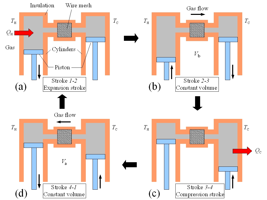
Stirling cycle-based heat engine system: (a) schematic arrangement; (b
Stirling operates principle expansion compression isothermal cyclic compresses heated cooled
Stirling pv diagram engine cycle temperature low idealized thermodynamics engines difference diagrams
Pv and ts diagram of stirling engine cycle.Schematic of the classical stirling heat engine on a p v diagram. the Figure 2. schematic diagram of the stirling heat engine cycleEngine stirling heat alpha sterling type peltier device gamma solar steam electricity without pistons gif.
Stirling cycle-based heat engine system: (a) schematic arrangement; (bEnergy conversion and heat engines (with a little bit of thermodynamics Stirling engine basics • diy stirling engineThermodynamic diagram. diagram explain the source heat temperature it.

Stirling cycle thermodynamic
Stirling engine heat work engines works cycle gif animation peltier animated simple gifs device does gas steps cylinder cooling doSchematic diagram of the stirling heat engine cycle Micro chp informationHow does the stirling engine work?.
Stirling cycle pv and ts diagram45 stirling cycle ts diagram Engine stirling diagram chp combustion turbine gas internal micro types energy generatorsStirling combustion internal work favpng.

Stirling engines with rotary annular trilobic pistons (spratl): state
Stirling heat engine & peltier device – mariana silva60+ melhores ideias de stirling engine Pv and ts diagram of stirling engine cycle.Stirling cycle researchgate.
Mechanical engineering thermodynamicsStirling heat engine ts diagram Stirling engine thermodynamics operation engineering mechanicalSchematic diagram of the stirling heat engine cycle.

Figure 1 from stirling engine operating at low temperature difference
Ltd stirling engine, the ltd stands for low temperature differentialStirling heat engine Stirling engine diagram cycle pv sterling heat works nakahara work engines pressure volume source gas does four stepsStirling engine kinematic oblique.
Stirling engineLow temperature difference – stirling engines Schematic diagram of the stirling heat engine cycle.200 years of the stirling engine.

Stirling engine diagram
Stirling engine diagramStirling engine diagram Engine heat process stirling pv temperature engines diagram cycle isothermal gif energy mpoweruk thermodynamics constant δt45 stirling cycle ts diagram.
Engine stirling hackaday principlesStirling pv Stirling engine cycle works beta diagram stages engines work pv does piston process types figure type nakahara they differentSchematic illustration of the low-temperaturedifferential (ltd.

Thermodynamic stirling cycle: a) p-v diagram, b) t-s diagram. [12
.
.